Circadian Sky

Installation Manual

⚠ IMPORTANT — Do not drill extra holes in the fixture. Use only the mounting holes already provided. LEDs and circuit boards run along the edges, and drilling additional holes can permanently damage the fixture.

What is in the box

1x Circadian Sky light fixture

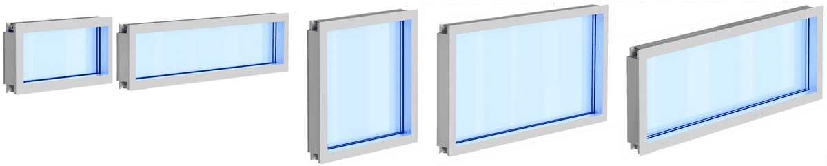
Circadian Sky Fixture Sizes

Optional accessories

(Available from Innerscene)

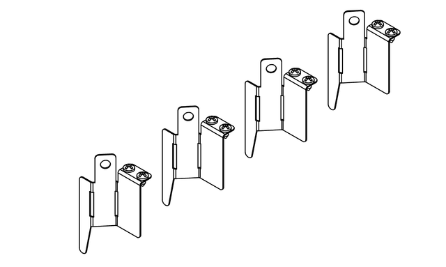
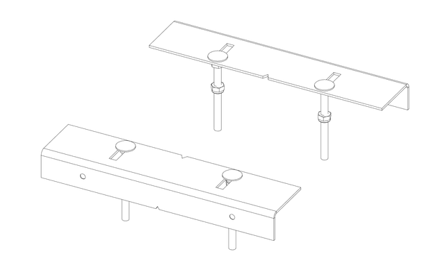
Spec code "GC" or "RG" (Grid Clips)

Brackets

Grid Mounting Kit

CS22NA, CS24NA, CS12NA, CS14NA

  • 4x tee grid clips (9/16" or 15/16")
  • 8x self-tapping screws

Spec code "JB" for 2x2 or 2x4 fixtures

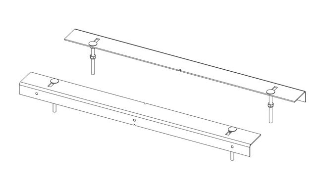
Two Foot Joist

2-Foot Joist Mounting Kit

CS22NA, CS24NA

  • 2x 2' joist brackets
  • 4x M6 bolts, nuts, lock nuts

Spec code "JB" for 1x2, 1x4, or 1.5x4 fixtures

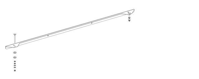
One Foot Joist

1-Foot Joist Mounting Kit

CS12NA, CS14NA, CS154NA

  • 2x 1' joist brackets
  • 4x M6 bolts, nuts, lock nuts

Spec code "SM" (Surface Mount)

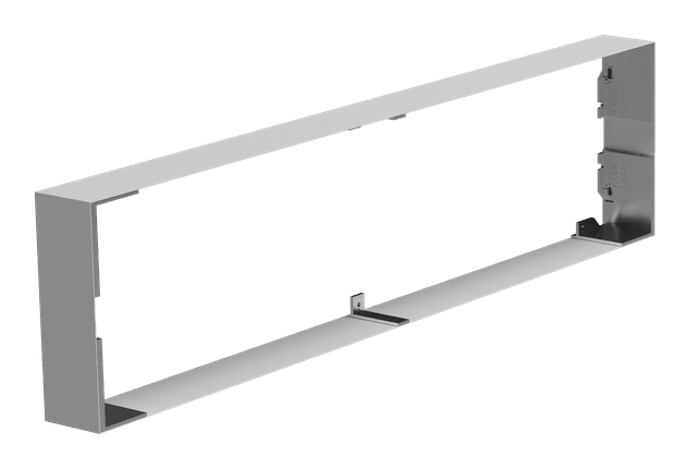
Surface Mount Kit

Surface Mount Kit

CS22NA, CS24NA, CS12NA, CS14NA, CS154NA

  • 1x surface mount frame (ships pre-attached to fixture)
  • Mounting hardware included

Cleaning: Circadian Sky uses standard tempered float glass and can be cleaned with any standard glass or window cleaner. Glass ratings & certifications →

Recommended tools and materials for ACT/Grid/Suspended ceiling and regress lay-in (RG) installs

(Supplied by others)

  • Large flat head screwdriver (to open K.O.)
  • Pozidriv screwdriver or Pozidriv screwdriver bit (for Grid clips screws)
  • 12-Gauge (1.5mm) hanger wire
  • 12-2 or 14-2 WG NM-B Romex and 1/2 in. Romex Electrical Wire Clamp. Suitable for use with Flexible Metal Conduit (FMC) and Squeeze Connector. 1/2 in. Knockout 90-Degree Connectors are required for tight two dimensional arrays.
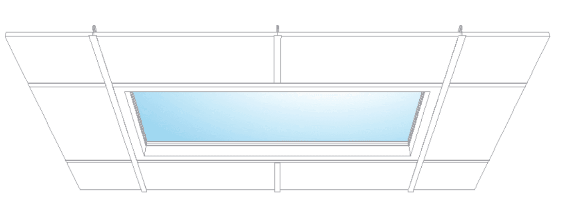
2x4 Grid
Circadian Sky 1x4 Armstrong Techzone installation

Recommended tools and materials for drywall/plasterboard installs

(Supplied by others)

  • M6 hexagonal nut driver (nut spinner) with 10mm (13/32 in.) hex size
  • Drywall saw
  • Laser level (to align cut-out or when installing multiple fixtures)
  • Tape measure
  • Large flat head screwdriver (to open K.O.)
  • Pozidriv screwdriver or Pozidriv screwdriver bit (for wood screws)
  • 6x #10 (5mm) countersunk wood screws for wood joists, or self-tapping/self-drilling screws (e.g. MF20 wafertek screws) for metal channels.
  • 12-2 or 14-2 WG NM-B Romex and 1/2 in. Romex Electrical Wire Clamp. Suitable for use with Flexible Metal Conduit (FMC) and Squeeze Connector. 1/2 in. Knockout 90-Degree Connectors are required for tight two dimensional arrays.
Circadian Sky Wall Installation

Individual drywall/plasterboard installations with joists

Joist Mounting Kit supplied when spec code "JB" is used for mounting option. This method applies to both wall and ceiling installations.

Individual Drywall Joists

Steps:

  1. Make cut-out in drywall.
  2. For remodelling, existing joists may need to be modified with extra joist headers. Secure Joist mounting brackets to joist or channel.
  3. Pull power or dimming wires to Primary fixture.
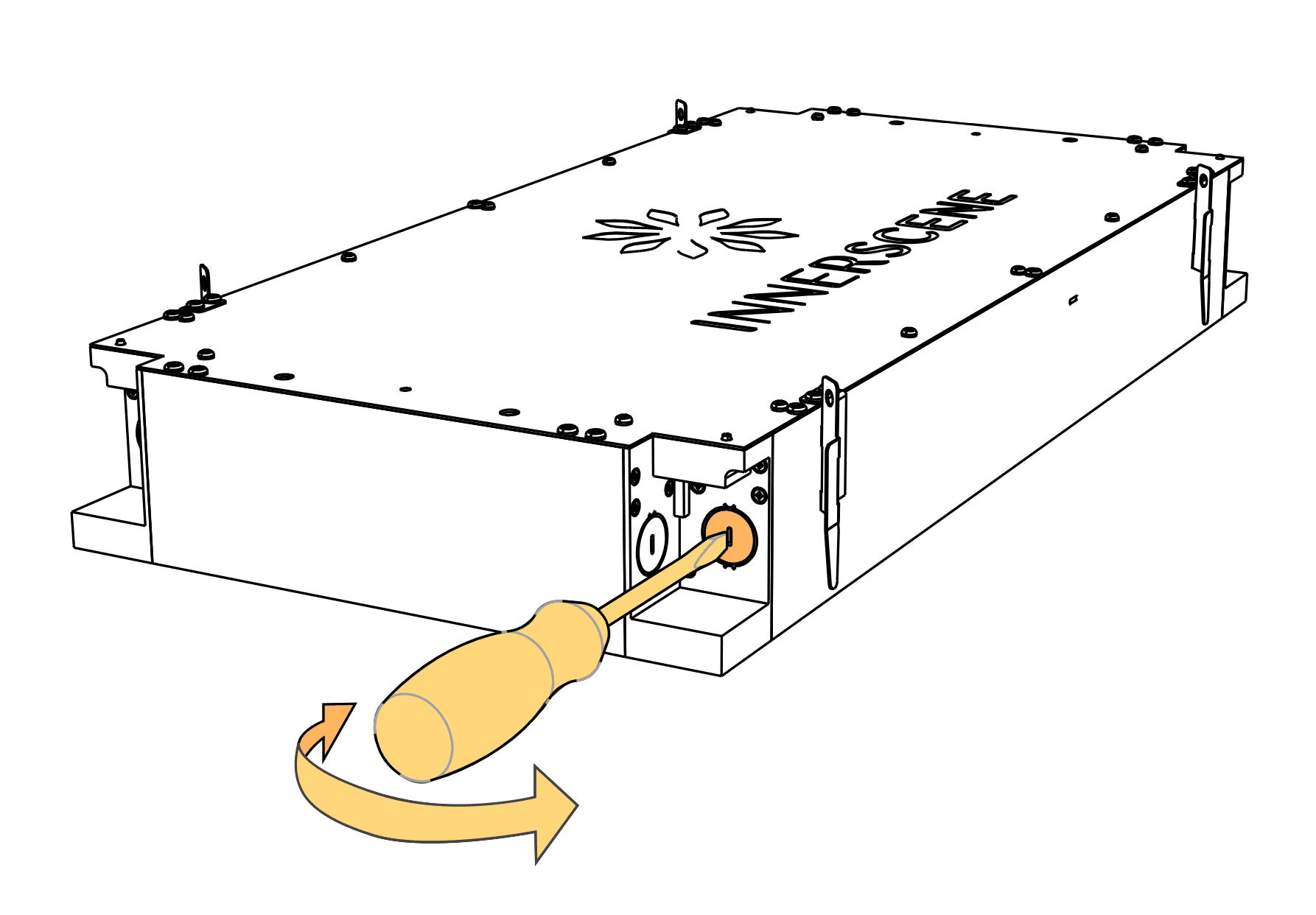
  4. Break 3/8” K.O. (Knock-Outs) using a flat head screw driver and connect wires.
  5. Raise fixture until bottom of fixture is level with finished ceiling.
  6. Secure fixture to threaded bolts using hex nuts (M6 hex nut with 10mm or 13/32” AF width)
  7. Clip safety harness of Drywall trim to fixture. Snap-fit Drywall trim to fixture.

Individual drywall/plasterboard installs without wood joists

Individual Drywall Install

Steps:

  1. Make cut-out in drywall.
  2. Install fixing points to structure (concrete ceiling / beams / structural channels etc.)
  3. Connect threaded rods to fixing points. Either 1/4" or M6 threaded rods are suitable.
  4. Pull power or dimming wires to Primary fixture.
  5. Break 3/8" K.O. (Knock-Outs) using a flat head screw driver.
  6. Raise fixture until bottom of fixture is level with finished ceiling.
  7. Secure fixture to threaded rods using hex nuts. Locking nuts are optional.
  8. Clip safety harness of Drywall trim to fixture. Snap-fit Drywall trim to fixture.

ACT/Grid/suspended ceilings installations

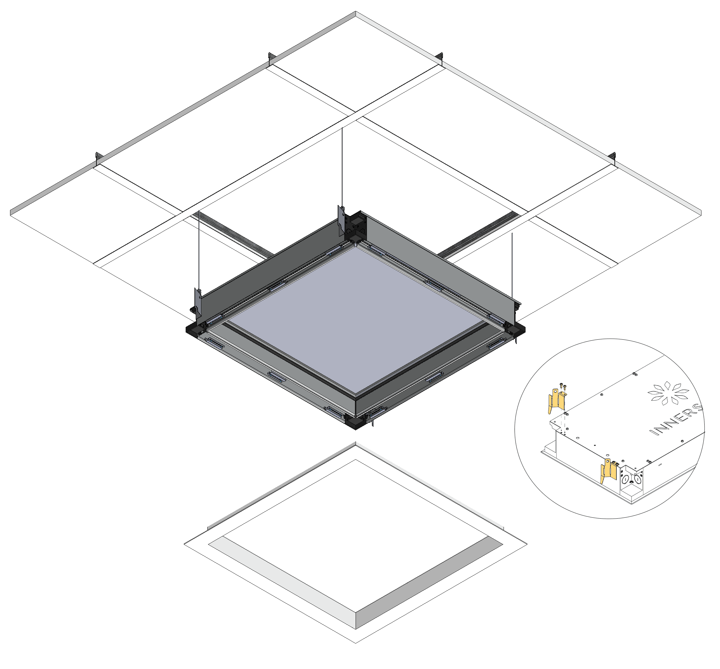
Grid Clip Mounting Kit supplied when spec code "GC" or "RG" is used for the mounting option.

Grid ACT Drawing

Steps:

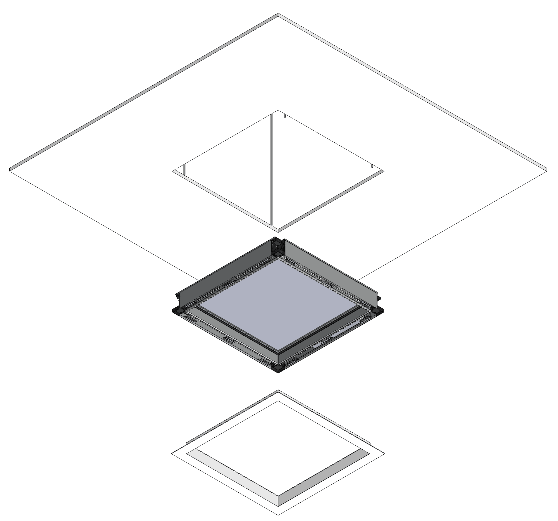
  1. Remove existing mineral tiles (if applicable)
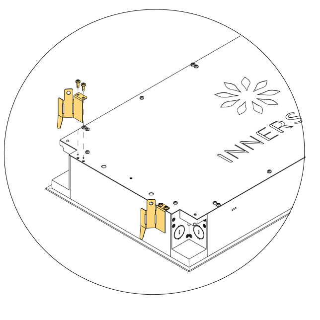
  2. Screw Grid clips to back of fixture using self-tapping screws (provided)
  3. Snap-out fixture trim and open K.O. (Knock-Outs)
  4. Connect building power and dimming wires (primary fixture only) to fixture
  5. Snap-in fixture trim
  6. Lay-in fixture above ceiling grid, align Grid clips to bulb of main runners/beams
  7. Attach #12 hanger wires (if deemed necessary, fixture weighs 26 lbs per 2’x2’ size)

Regress lay-in (RG) drywall coffer installations

Applies when spec code "RG" is used for the mounting option. Fixtures are laid into a site-built drywall coffer, similar to lay-in ceiling tiles, resting on perimeter supports with no load-bearing mounting kit. The included grid clips are not load-bearing here; their attachment points accept hanger wire so each fixture can be tethered to the structure above to prevent it from falling into the room during seismic activity, while staying removable from below. These pages cover the required overhead clearance, the coffer construction and sizing, and the installation steps; wiring and controls are covered in the standard sections of this manual.

Regress lay-in (RG): clearance for the lay-in rotation

The fixture housing is wider than the window opening, so it only passes through the coffer tilted. It threads up through the window at a steep roll, then levels out while its lower edge stays dipped in the opening, sliding sideways over the ceiling as it flattens. The matrix below gives the minimum clearance between the finished ceiling and the structure above for this maneuver, including a 1" working margin. It assumes open plenum space beside the coffer; deeper coffers need more room almost inch for inch. Thread fixtures through a multi-cell opening lengthwise (insert the last two fixtures together before sliding the second-to-last into its cell).

Fixture sizeHousing cross-sectionWindow opening2×4 + 5/8″ drywall (4-1/8″ regress)2×6 + 5/8″ drywall (6-1/8″ regress)2×12 + 5/8″ drywall (11-7/8″ regress)
CS14 / CS154 / CS24 side by side46-7/8″ × 3-5/16″43-3/4″≥ 9″≥ 11″≥ 16-3/4″
CS22 · CS24 end to end · CS12 side by side23-1/4″ × 3-5/16″20-1/8″≥ 9-1/2″≥ 11-1/2″≥ 17-1/4″
CS154 end to end17-1/4″ × 3-5/16″14-1/8″≥ 9-1/2″≥ 11-1/2″≥ 17-1/4″
CS12 / CS14 end to end11-1/4″ × 3-5/16″8-1/8″≥ 10″≥ 12″≥ 17-3/4″

Clearance is measured from the finished ceiling face to the underside of the structure above. Rule of thumb: regress depth plus about 6". Use the interactive simulation on the next page to scrub through the maneuver; the worst-case drawings show the binding position for each size.

Cross-section drawing of a CS12 or CS14 fixture rolled 35 degrees, lower edge dipped through the window, at the tightest point of the level-out
Worst-case position, 11-1/4″ crossing the slot: CS12 / CS14 end to end

Regress lay-in (RG): interactive clearance simulation

Scrub the time slider to step through the lay-in maneuver, drag to orbit, and switch fixture size, array orientation and regress depth to see the clearance each combination needs. The printed manual shows the worst-case side profile for the selected configuration.

Regress lay-in (RG): worst-case positions, continued (4-1/8″ regress build-up)

Cross-section drawing of a CS154 fixture rolled 26 degrees, lower edge dipped through the window, at the tightest point of the level-out
Worst-case position, 17-1/4″ crossing the slot: CS154 end to end
Cross-section drawing of a CS22 or CS24 fixture rolled 20 degrees, lower edge dipped through the window, at the tightest point of the level-out
Worst-case position, 23-1/4″ crossing the slot: CS22, CS24 end to end, CS12 side by side (see the sizing table for the 46-7/8″ side-by-side crossing)

Regress lay-in (RG): array with framing and drywall

Cross-section through the coffer with a fixture installed: structure, hanger wire, grid clip, housing resting on perimeter straps, framing and drywall
Coffer cross-section with fixture installed (CS12 shown; see the sizing table for all sizes)
Reflected ceiling plan of six CS12 fixtures with drywall
Reflected Ceiling Plan (RCP) with drywall, six-CS12 worked example

Regress lay-in (RG): materials and coffer sizing

Fixture dimensions

Fixture sizeVisible glass (W × L)Overall including trim (W × L)
CS12 (1×2 ft)8.33″ × 20.14″11.93″ × 23.74″
CS14 (1×4 ft)8.33″ × 43.76″11.93″ × 47.36″
CS154 (1.5×4 ft)14.12″ × 44.12″17.72″ × 47.72″
CS22 (2×2 ft)20.14″ × 20.14″23.74″ × 23.74″
CS24 (2×4 ft)20.14″ × 43.76″23.74″ × 47.36″

Trim is 1.80" wide on all sides and overlaps a ceiling cut-out by up to 0.26" per side; housing depth is 3.60" (3.68" minimum recess including the rear screw heads). When tiling multiple fixtures, allow an additional 1/16" margin between adjacent trims. Dimensions per the Circadian Sky Dimensional Drawings (all sizes).

Typical materials

  • Drywall: e.g. 5/8" gypsum board
  • Well liner: e.g. 1/2" gypsum board on the reveal walls, finished flat white to match the trim
  • Framing: e.g. 2" × 4" lumber
  • Perimeter support: e.g. Simpson Strong-Tie 25-ft 16-gauge galvanized steel coiled strap, wood to wood, model CS16-R (Lowe's item #1944384)

Coffer sizing for every fixture size

The six-CS12 array in the figures is a worked example; the same detail applies to every Circadian Sky size. Housing depth is 3-5/16" for all sizes. The window opening is the finished glass-flush slot; butted fixtures share one continuous slot that spans from glass to glass across the butt joints (the six-CS12 example's group window is 140-5/8" × 8-1/8"). Where the well walls are lined with drywall, frame the rough opening larger by twice the liner thickness so the finished opening still matches these values. The Circadian Lab previews compute the slot for any array automatically.

Fixture sizeHousing (W × L)Window opening (W × L)WeightMin clearance, end to end*Min clearance, side by side*
CS12 (1×2 ft)11-1/4″ × 23-1/4″8-1/8″ × 20-1/8″7.3 lbs≥ 10″≥ 9-1/2″
CS14 (1×4 ft)11-1/4″ × 47-1/4″8-1/8″ × 44-1/8″25.1 lbs≥ 10″≥ 9″
CS154 (1.5×4 ft)17-1/4″ × 47-1/4″14-1/8″ × 44-1/8″33.7 lbs≥ 9-1/2″≥ 9″
CS22 (2×2 ft)23-1/4″ × 23-1/4″20-1/8″ × 20-1/8″24 lbs≥ 9-1/2″≥ 9-1/2″
CS24 (2×4 ft)23-1/4″ × 47-1/4″20-1/8″ × 44-1/8″43.7 lbs≥ 9-1/2″≥ 9″

* Overhead clearance for the lay-in rotation at the 4-1/8" example regress, by array orientation: end to end puts the short housing side across the slot, side by side the long side (a wider crossing dimension rolls less, so it needs slightly less height). For deeper regress values see the clearance matrix.

Regress lay-in (RG): installation steps

Installation steps

  1. Prepare the drywall coffered ceiling: confirm the framing safely supports the full array weight plus drywall, the finished drywall is straight and level along the coffer, perimeter support is installed around the opening, and overhead clearance meets the clearance matrix. Line the well walls (the vertical reveal between the finished ceiling and the fixture) with drywall, primed with a stain-blocking primer and finished flat white to match the trim. Frame the rough opening larger than the finished window opening by twice the liner thickness (e.g. 1" wider each way for 1/2" board) so the finished opening still meets the clearance matrix. Finish the coffer edges with a sharp drywall corner bead (e.g. Trim-Tex RJ10LP or similar) for a crisp shadow line.
  2. Pull power and control wiring to the fixture locations (see the wiring section of this manual).
  3. Lay in each fixture, similar to a lay-in ceiling tile, by angling it through the coffer opening as shown in the worst-case drawings and the interactive simulation. Thread fixtures through a multi-cell opening lengthwise; insert the last two fixtures together before sliding the second-to-last into its cell.
  4. Move each fixture into its final position resting on the perimeter support, then connect power and controls.
  5. If hanger wire is required (so the fixture cannot fall into the room during seismic activity): before laying the fixture in, attach the wire from the grid-clip attachment points to the structure above with plenty of slack. Once the fixture is in position, push it upward into the cavity to open hand access above the housing and tighten the hanger wire, then lower it back onto the perimeter support.

To remove a fixture later: push it up into the cavity, loosen the hanger wire, then rotate the fixture back out of the ceiling the same way it was laid in.

Grid clips screwed to the back of the fixture with the provided self-tapping screws
Grid clips screw to the back of the fixture (self-tapping screws provided); their slots take the hanger wire.

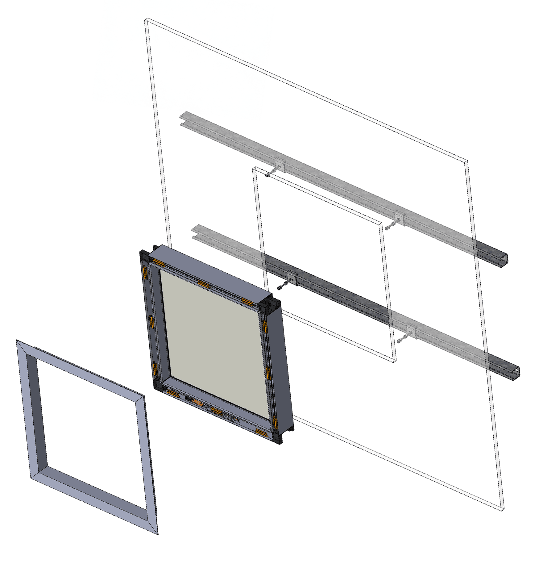
Individual vertical (In-wall) installations

Inwall Installation

Steps:

  1. Make cut-out in drywall.
  2. Install Unistrut channels (horizontally for wall applications)
  3. Install 1/4” or M6 threaded rod to align with mounting holes in fixure
  4. Install 2x backing nuts per threaded rod to set install depth
  5. Pull power or dimming wires to Primary fixture
  6. Break 3/8” K.O. (Knock-Outs) using a flat head screw driver
  7. Ease fixture into position until front is flush with finished drywall. Adjust backing nuts if needed
  8. Secure fixture to threaded rods using hex nuts. Locking nuts are optional
  9. Clip safety harness of Drywall trim to fixture. Snap-fit Drywall trim to fixture

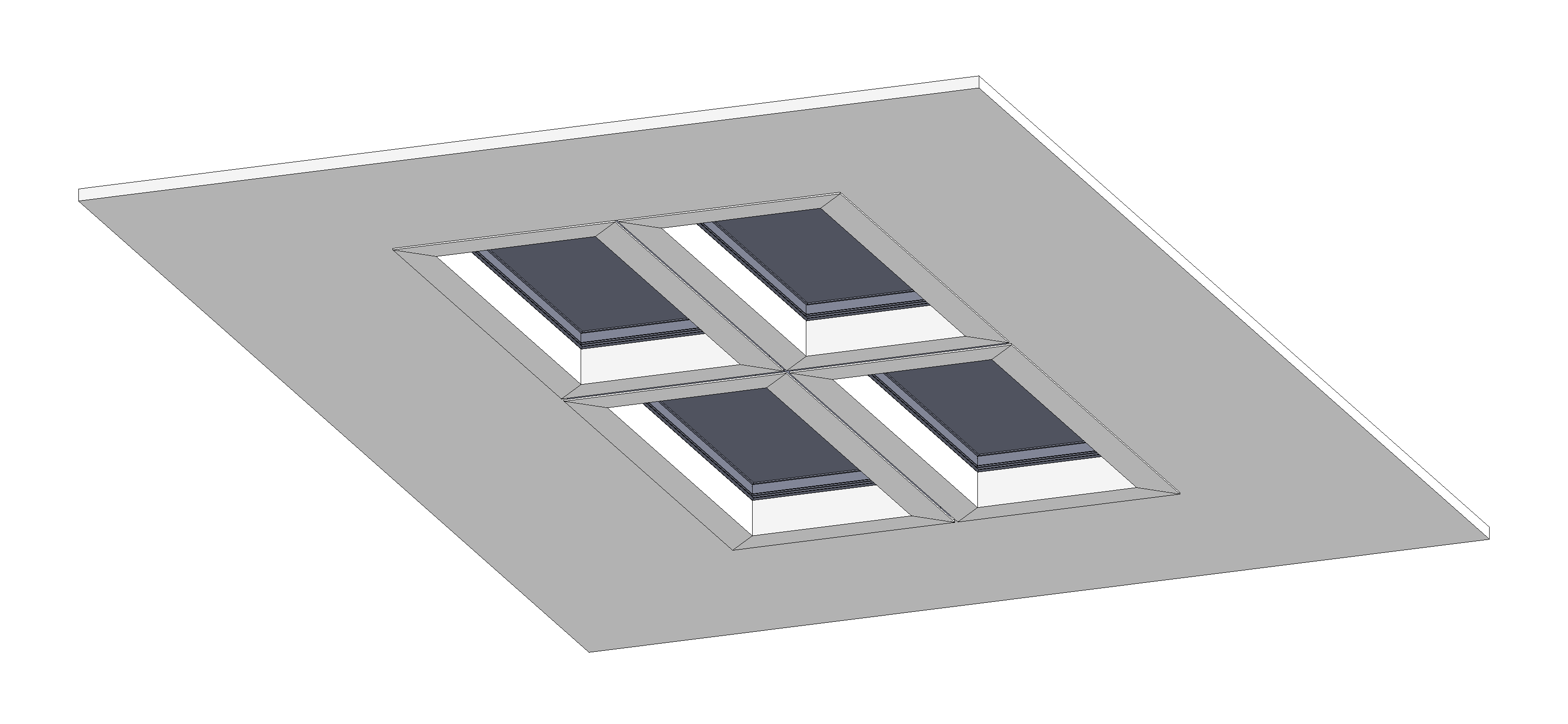
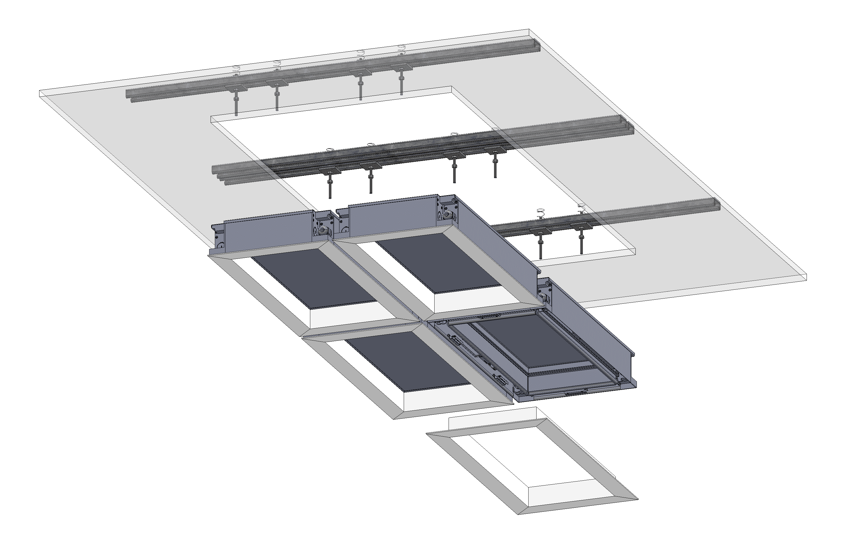
Tight array with drywall/plasterboard ceilings or walls installations

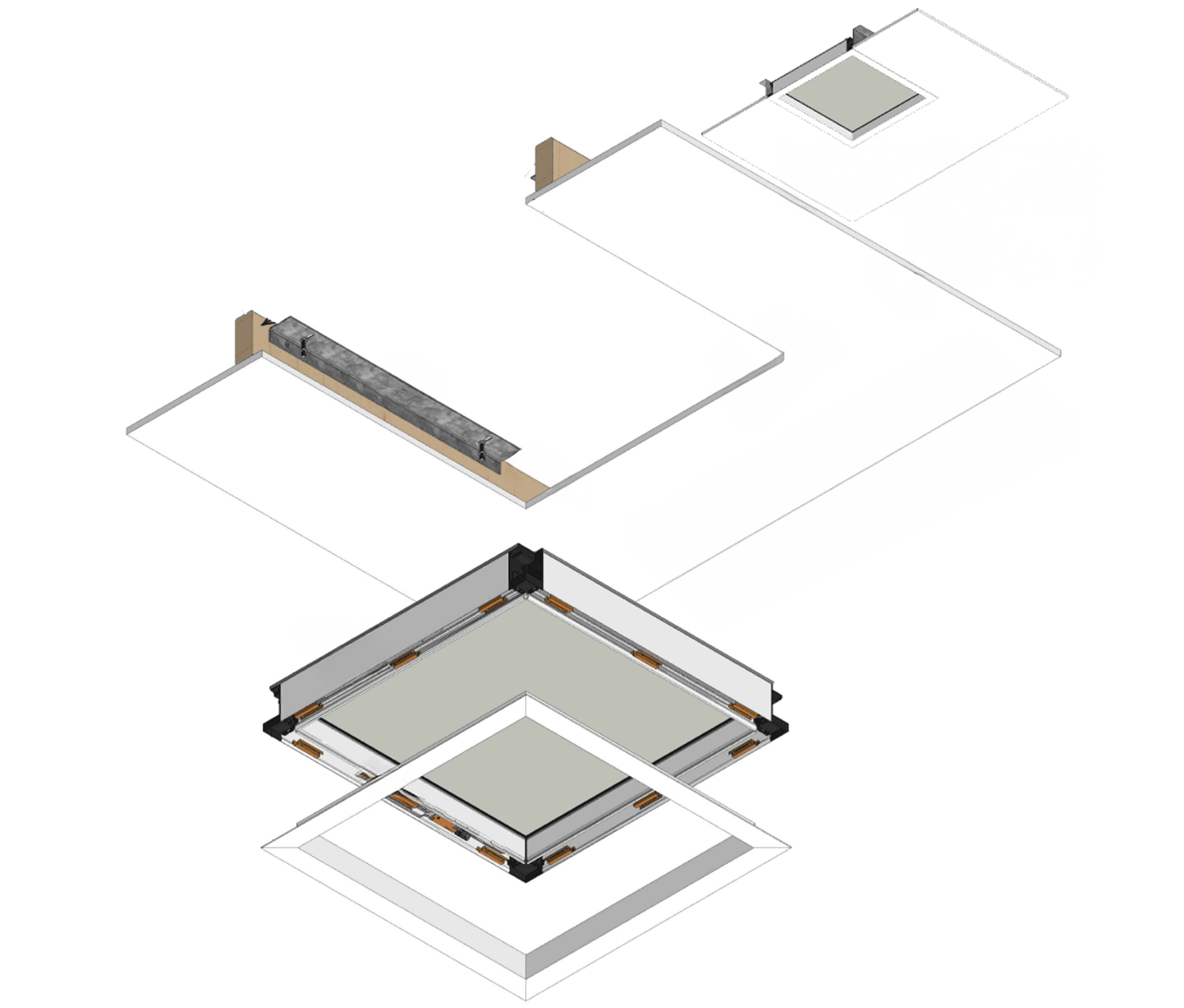
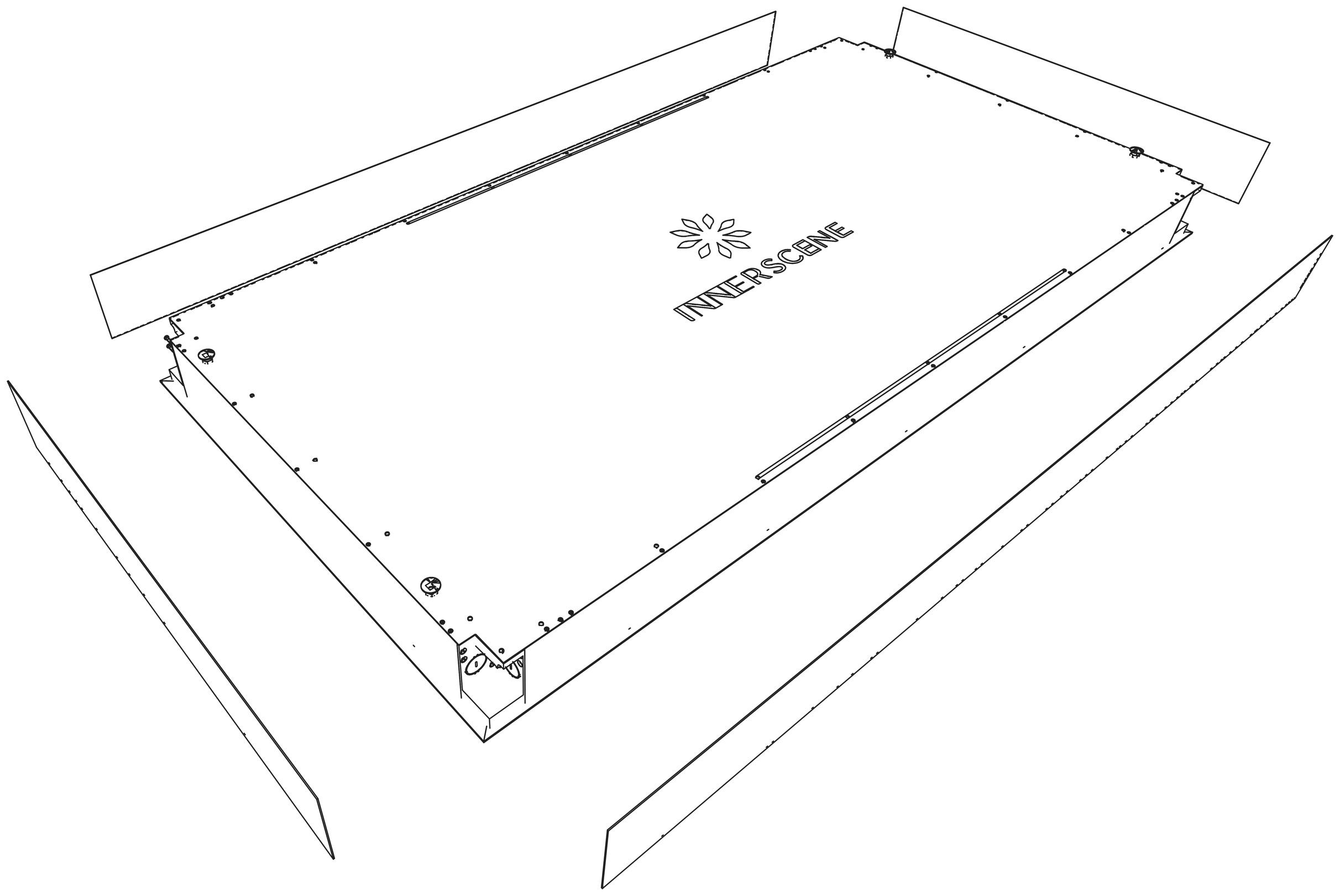
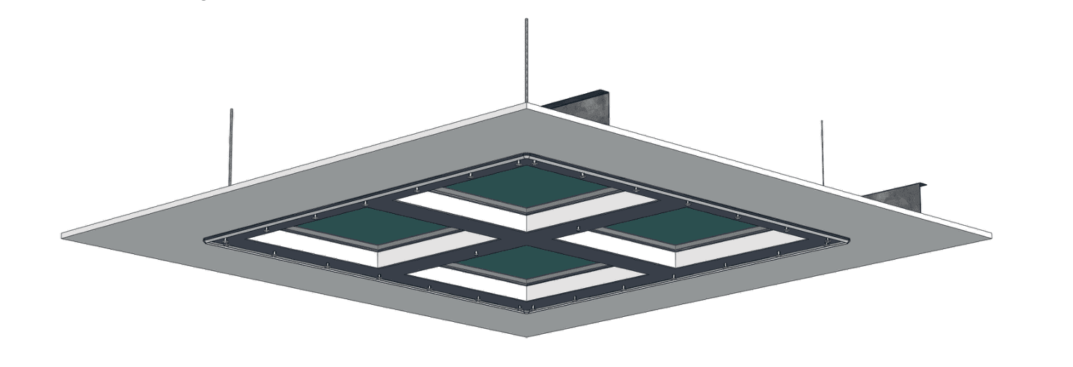
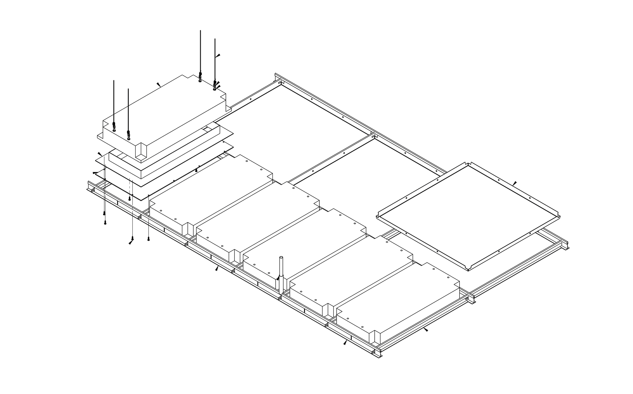
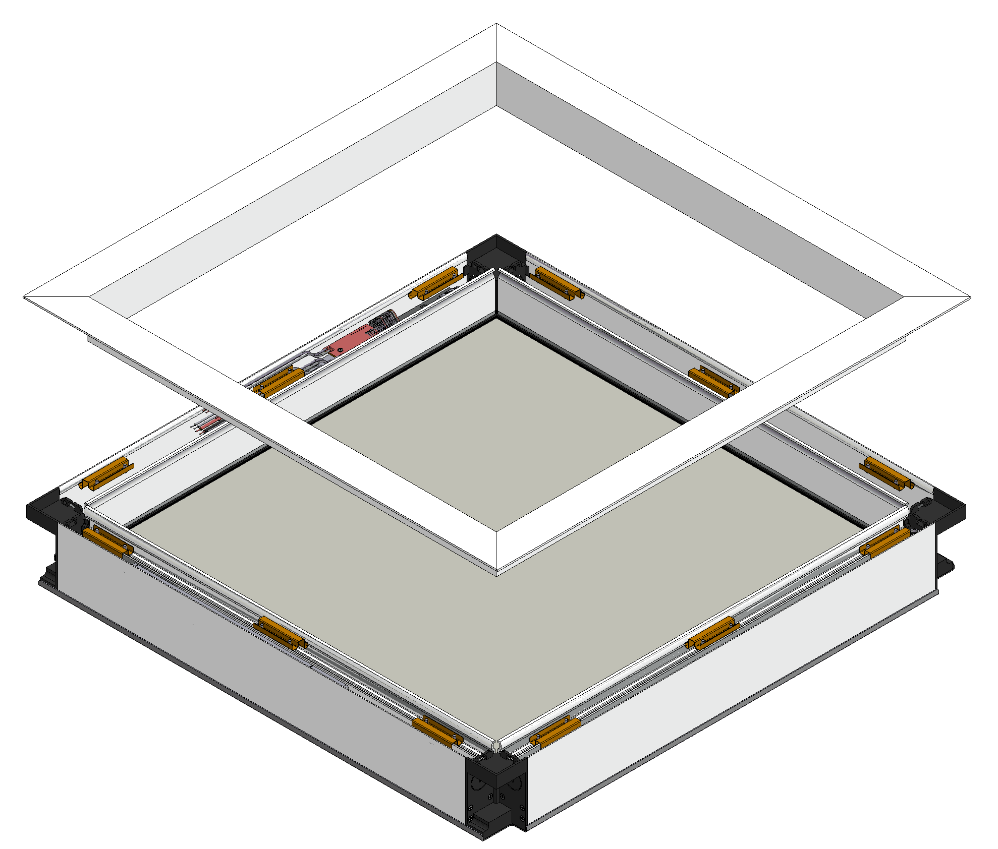
2x2 Array View
2x2 Exploded View

Steps:

  1. Make cut-out in drywall.
  2. Install Unistrut channels (horizontally for wall applications)
  3. Install 1/4” or M6 threaded rod to align with mounting holes in fixure
  4. Pull power or dimming wires to Primary fixture
  5. Break 3/8” K.O. (Knock-Outs) using a flat head screw driver
  6. Raise fixture until bottom of fixture is level with finished ceiling.
  7. Secure fixture to threaded rods using hex nuts. Locking nuts are optional
  8. Clip safety harness of Drywall trim to fixture. Snap-fit Drywall trim to fixture

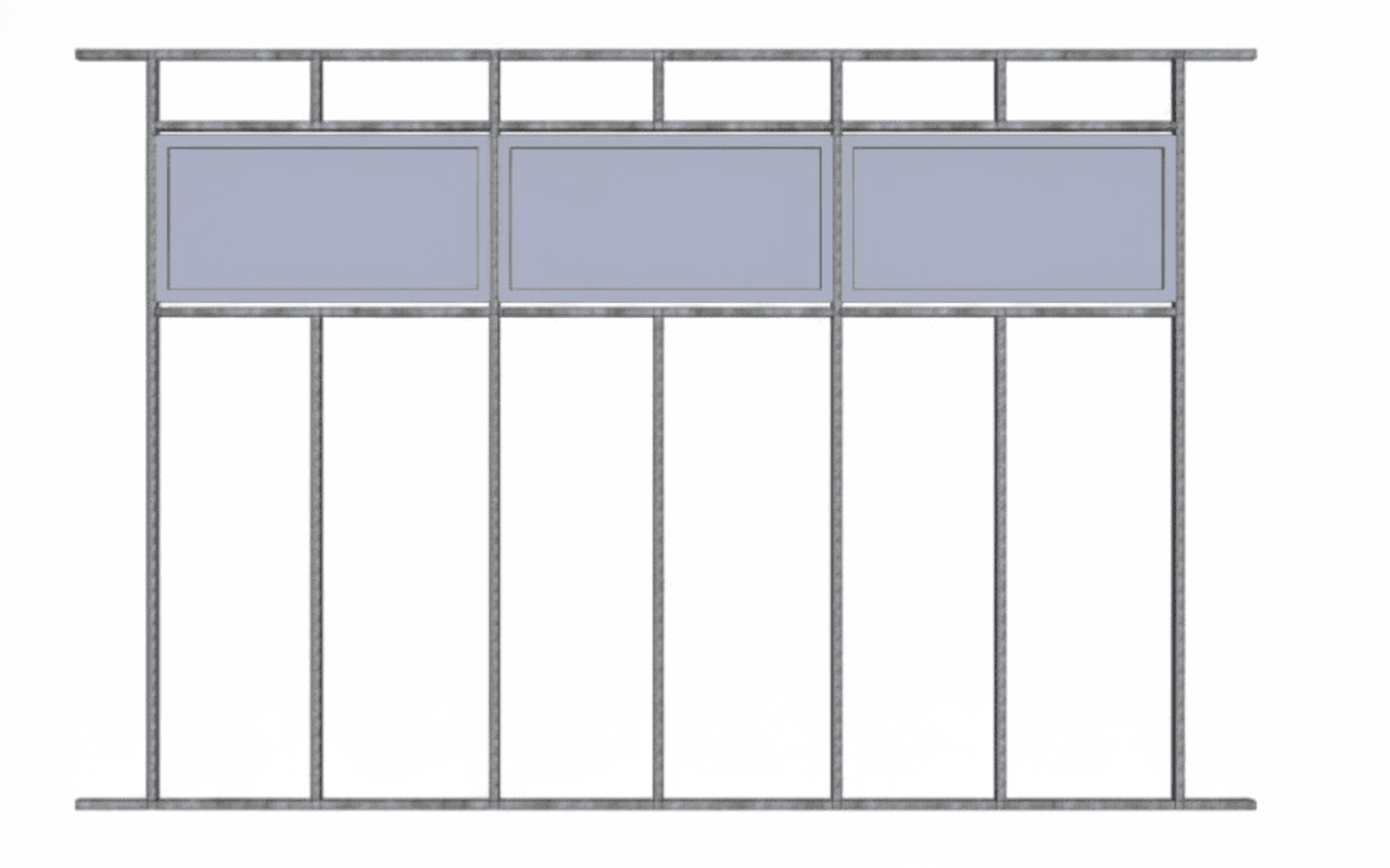
Wall tight array with metal studs (1×4, 2×4, 1.5×4 fixtures)

For landscape orientation 4ft fixtures (CS14, CS24, CS154) in a tight wall array using metal stud framing.

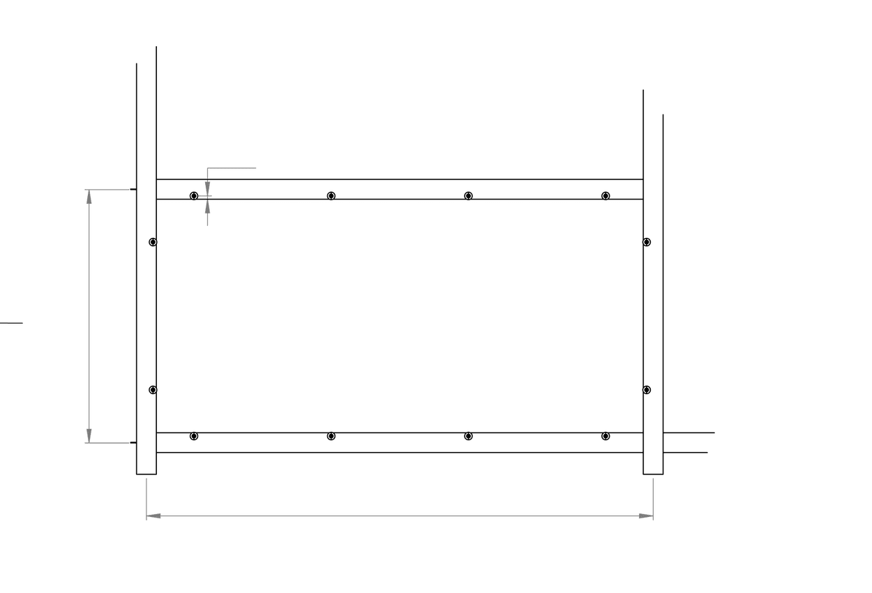
Front View (Without Drywall)

Wall Tight Array - Front View Framing

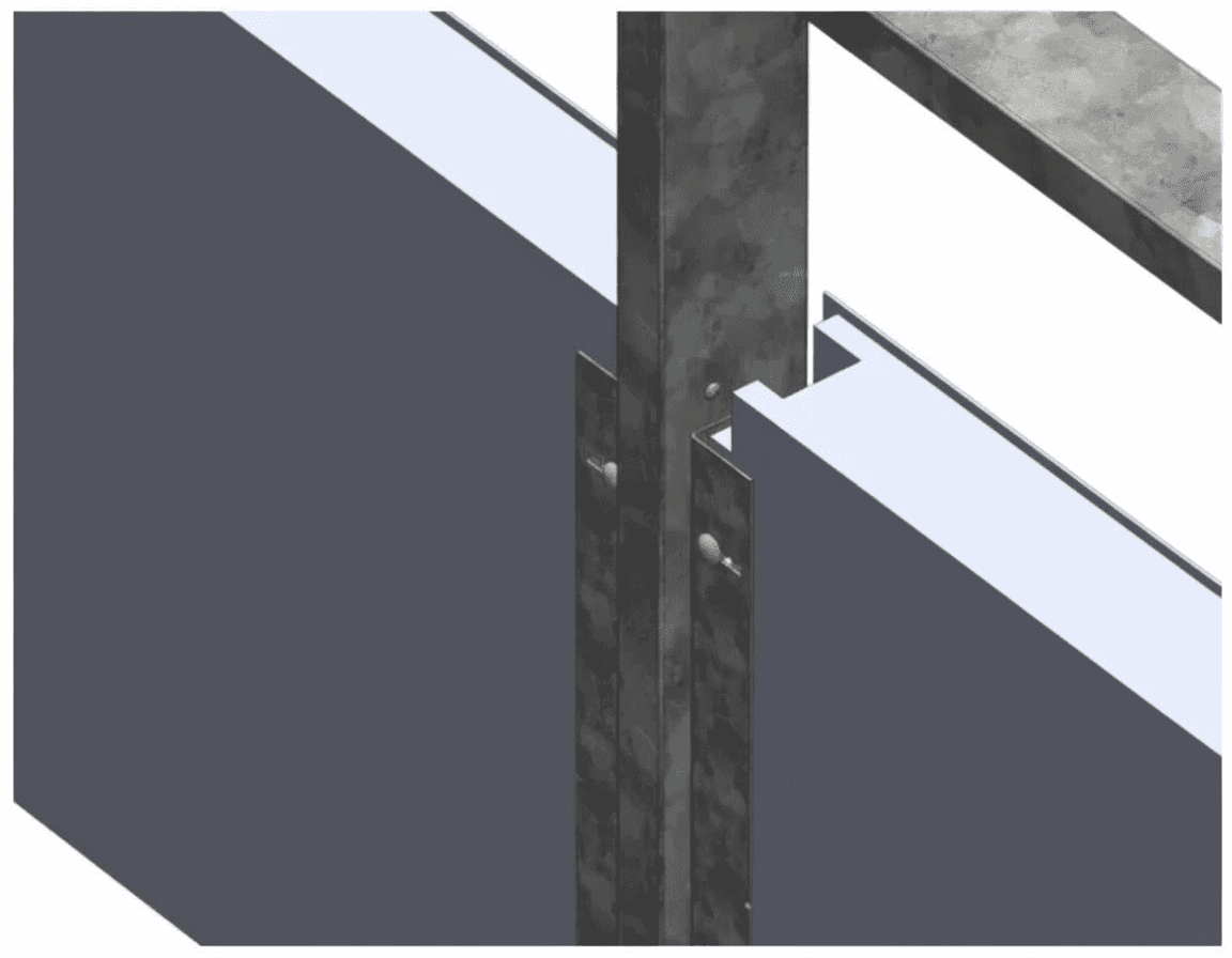
Mounting Close-ups

Wall Tight Array - Close-up without furring strip
Wall Tight Array - Close-up with furring strip

Drywall Requirements

ThicknessMinimum ½"
Cut-out per fixture23"-1/4 (W) × 46"-7/8 (L)

Materials (by others)

Structural Stud3"-5/8 (ClarkDietrich 362S137-43-P)
Structural Track3"-5/8 (ClarkDietrich 362T125-33)
Furring Strip2" lumber (2×2×8ft)
Wood ScrewsRound head (McMaster 98685A840)
Bracket Screws3× No. 6 screws (countersunk)

Surface mount installations

Surface Mount Kit supplied when spec code "SM" is used for mounting option.

⚠ Safety Note: Gloves are recommended when handling the surface mount kit as edges may be sharp.

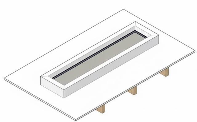
Surface Mount - Preview

Step 1: Locate and Mark Studs

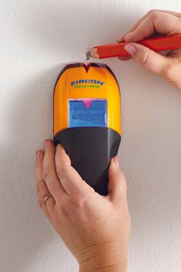
For remodeling/retrofit, use a stud finder to locate and mark studs. Mark and measure actual on-center stud spacings (OC). Typical spacing is 16" O.C.

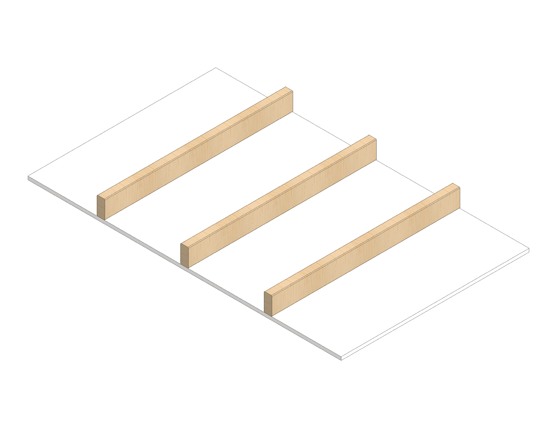
Surface Mount - Joists Framing
Surface Mount - Stud Finder

Stud Finder: Use a quality stud finder to locate wood joists behind drywall. Mark both edges of each stud to ensure accurate centering of screws.

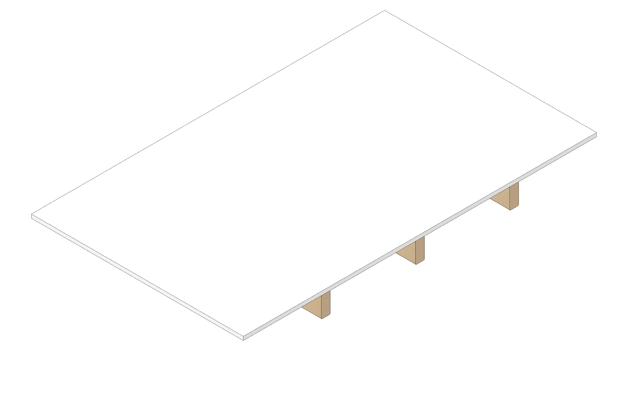
Surface Mount - Drywall with Marked Studs

Surface mount installations (continued)

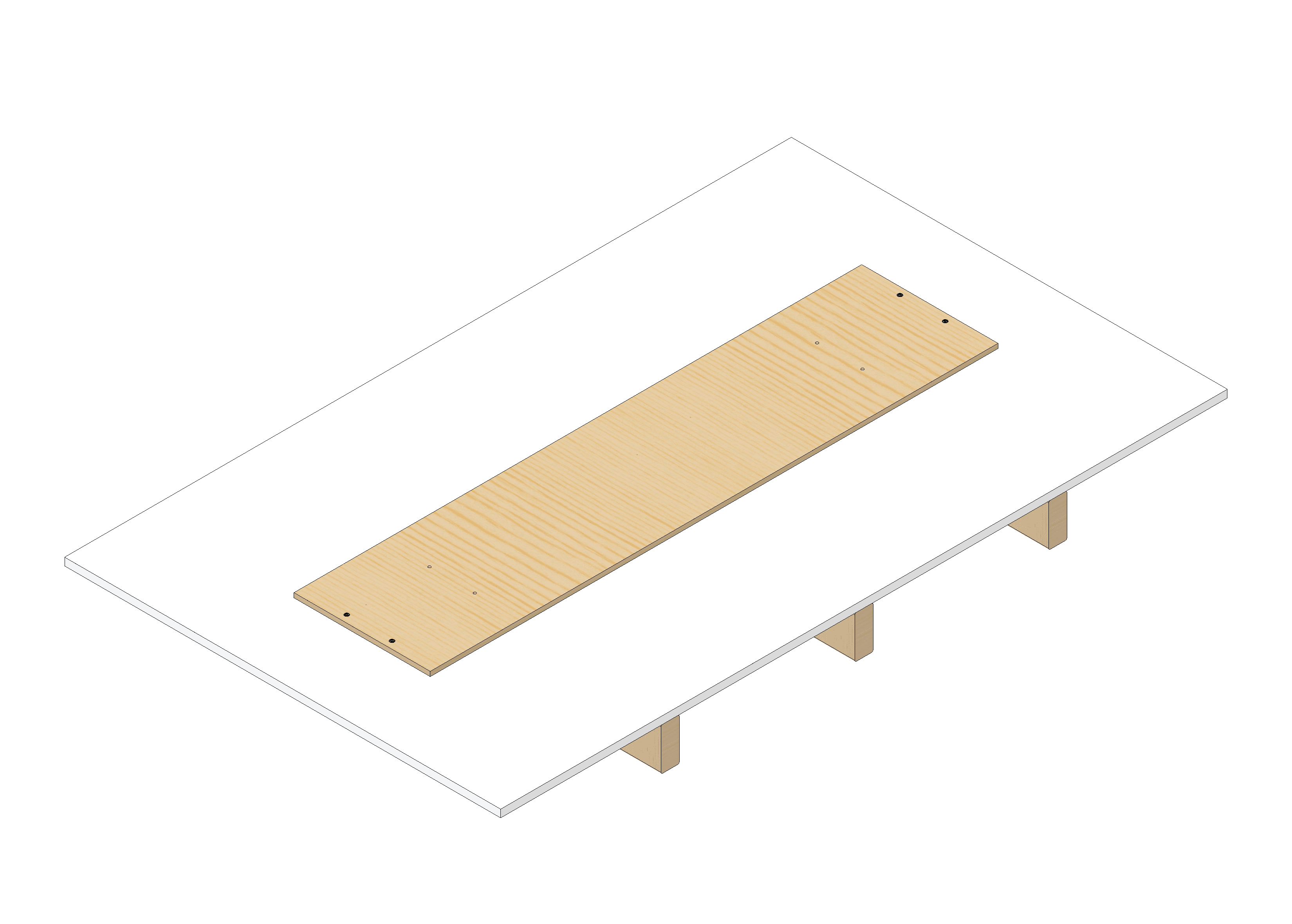
Step 2: Cut and Mount Plywood Backing Plate

Note: Plywood backing plate and mounting hardware supplied by others.

Equipment and Parts:
• ≥4x Wood screws (#12 x 2" Phillips Pan Head Wood Screws, e.g., Homedepot #802572 or Lowes #57385)
• 4x 1/4-in 1-in Self-Drilling wood screws (e.g., Strong-Tie, Homedepot, Lowes #SDS25112-R25)

Steps:
1) Cut a 3/8" thick plywood back plate to suit the fixture size (see table below).
2) Mounting holes can be with 1/4" screws or bolts. 1/4"-20 Machine screws and wood insert nuts can be used if junction box requires frequent inspections as wood screw holes can be damaged over time. Self-drilling wood screws are faster.
3) Pilot holes into wood are not required for mounting holes if using self-drilling wood screws. However, drilling through drywall with a 1/4" is recommended to avoid lifting.

Fixture
size
Backing plate minimum sizeMounting holes
Length(L)Width(W)ThicknessXYDrill bit
1x223"-1/25"3/8"3.74" (95mm)22.05" (560mm)23/64"
1x447"5"3/8"3.74" (95mm)45.67" (1160mm)23/64"
2x223"-1/417"3/8"15"-3/4 (400mm)22.05" (560mm)23/64"
1.5x447"5"3/8"3.74" (95mm)45.67" (1160mm)23/64"
2x447"17"3/8"15"-3/4 (400mm)45.67" (1160mm)23/64"

Note: Only 3/8" plywood is recommended for the backing plate. 1/4", 1/2", and 3/4" thicknesses are NOT suitable.

Surface Mount - Plywood Backing Plate

Surface mount installations (continued)

Step 3: Mount Fixture and Close Trim

Mount the fixture to the plywood backing plate using the 4 mounting holes at the corners. Once secured, close the front trim to complete the installation.

Screw locations

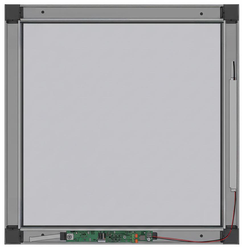
Circadian Sky - Overhead View with Mounting Holes

Complete installation by securing trim.

Note: Use 4 screws at the corner mounting holes. Select appropriate fasteners for your backing plate (wood screws, machine screws with nuts, etc.).

WIRING

Exclamation

IMPORTANT: READ ALL INSTRUCTIONS THOROUGHLY PRIOR TO INSTALLATION, USE QUALIFIED INSTALLERS/ELECTRICIANS, COMPLY WITH LOCAL ELECTRICAL CODES, RETAIN INSTALL MANUAL FOR REFERENCE.

Open Trim

Pull open the snap-fit trim

Snap-fit Trim

Break 1/2" K.O. (Knock-Outs)

Knockouts

Normal Power (All fixtures inc. Casambi)

Wiring 2

Using WAGO 221 Connectors: Lever-actuated connectors for tool-free wire splicing. To connect: Lift the orange lever, insert stripped wire (strip ~11mm / ⁷⁄₁₆"), then push lever down to lock. Clear housing allows visual confirmation of proper insertion.

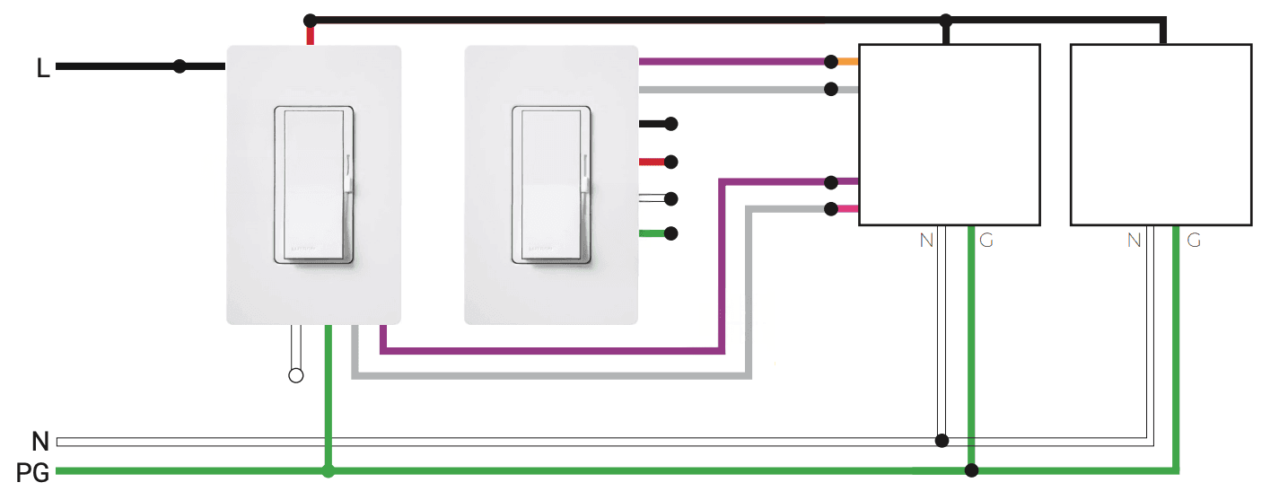
Dual Channel 0-10V (Primary fixture-only)

Dual Channel 0-10V Wiring

Both GND terminals are shared — if your dimmer has only 3 wires, one GND connection is sufficient.

DMX Tunable Sky (Primary fixture-only)

Wiring 4

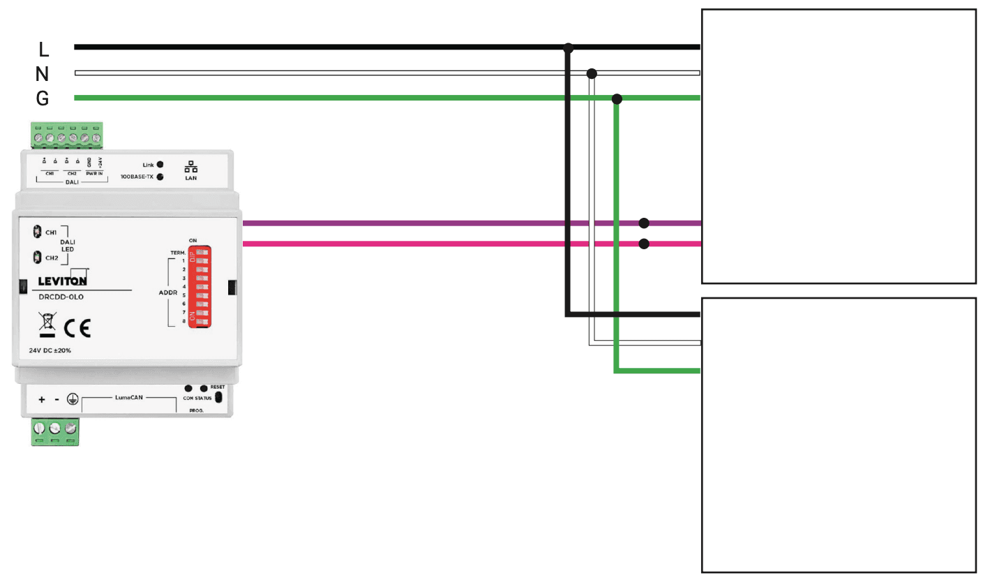
DALI-2 DT8 Tc Tunable Sky (Primary fixture-only)

Wiring 5
  1. Only Primary fixture have lighting control/dimming pigtails.
  2. Only 1no. Primary is sold per group/zone
  3. Casambi Primary fixture are wireless and does not require additional dimming wiring.
  4. Building wires to be 18-12 AWG when using the supplied Wago connectors.

Mounting Holes & Wiring Connections

⚠ IMPORTANT: Only use the existing mounting holes to secure the fixture. DO NOT drill additional holes — LEDs and circuit boards are located along the edges and drilling may cause permanent damage to the fixture.

Circadian Sky - Overhead View with Mounting Holes

Mounting Points

  • Use the 4 pre-drilled mounting holes at the corners to secure the fixture
  • Use appropriate fasteners for your ceiling type (wood screws, toggle bolts, etc.)
  • GC and RG installations: the mounting holes are not needed — the fixture lays onto the grid (GC) or rests on the coffer's perimeter support (RG)

Wiring Connections

  • Power input: Connect line voltage (120V/277V) to the AC/DC power supply
  • Ground: Connect building ground wire to the green ground screw
  • Control signals: Connect dimming wires (0-10V, DMX, or DALI) to the daughter board as applicable. 0-10V board terminals are labeled DIM, CCT, and GND.
  • Use the supplied Wago connectors for secure connections

Remote power supply installation

The 24 VDC power supply (PSU) ships integrated to the fixture by default. When spec code "REM"is selected, the PSU is shipped uninstalled so it can be mounted remotely (e.g. above the ceiling plenum, on a junction box, or in an accessible service area). Innerscene uses Mean Well SLD-50-24 (35–45 W fixtures) or SLD-80-24 (75 W fixtures) — both have the same terminal layout described below.

⚠ Voltage drop limit: The DC cable run from the remote PSU output to the fixture's internal controller board must not exceed 0.5 V drop at full load. Voltage drop above this threshold can cause dimming inconsistency, color shift, or controller brown-out.

Recommended cable AWG vs. one-way distance

Maximum one-way cable length per AWG that keeps round-trip voltage drop ≤ 0.5 V on the 24 VDC bus. Use stranded copper, twisted pair recommended. Values calculated at 25 °C — derate for higher ambient.

FixtureLoad @ 24 V18 AWG16 AWG14 AWG12 AWG10 AWG
1×2 (35 W)1.46 A26 ft (8.0 m)42 ft (12.8 m)67 ft (20.4 m)107 ft (32.6 m)171 ft (52.1 m)
2×2 / 1×4 / 1.5×4 (45 W)1.88 A20 ft (6.2 m)33 ft (10.0 m)52 ft (15.9 m)83 ft (25.3 m)132 ft (40.3 m)
2×4 (75 W)3.13 A12 ft (3.8 m)19 ft (6.0 m)31 ft (9.6 m)50 ft (15.2 m)80 ft (24.3 m)

Remote power supply installation (continued)

Installation steps

  1. Mount the PSU enclosure in an accessible, dry location with adequate airflow. Secure per local code; orient with vents unobstructed.
  2. Wire line-voltage AC input (110–277 VAC) to the PSU per the markings on the unit. Bond ground.
  3. Run the 24 VDC output from the PSU to the fixture's controller board. Size the conductors per the table above. Connect red wire to VIN and black wire to GND on the controller board.
  4. Use the supplied WAGO 221 connectors (or equivalent UL-listed connectors rated for the conductor size) at the fixture end.
  5. After power-up, verify ≥ 23.5 V at the controller board input terminals at full output.

⚠ Polarity is critical: Reversing the 24 VDC connections will damage the controller board and is not covered by warranty. Always verify red VIN and black → GND before applying power.

Power supply reference

Integrated PSU and controller board assembly inside the fixture, showing red DC+ wire routing from PSU output to controller VIN terminal

Mean Well SLD-50-24 / SLD-80-24 PSU body — top view. End flanges provide mounting holes; line-voltage AC terminals are on one end, 24 VDC output (red + / black −) on the other. For REM installations, the PSU is removed from its carrier and mounted remotely.

Wiring diagram

Mean Well SLD-50-24 / SLD-80-2424 VDC outputAC IN110–277 VACLNV+V−Controller Board(inside fixture)VINGNDRED (+)BLACK (−)Sized per AWG table — keep V drop ≤ 0.5 V

Schematic only — terminal layout reflects Mean Well SLD-50-24 / SLD-80-24.

⚠ Wireless Group Installation

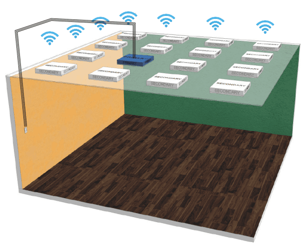
Unlike typical fixtures that each require individual control wiring, Innerscene uses wireless groups to reduce installation cost and ensure perfect synchronization. Each group has one Primary fixture (with control wiring) that wirelessly coordinates all Secondary fixtures in the group—eliminating voltage drop issues and ensuring all fixtures match brightness and color exactly.

Each wireless group is typically controlled by one wall dimmer. The dimmer connects to the Primary fixture, which wirelessly controls all Secondary fixtures in that group:

Group 1 (Example)ONOFFWall DimmerPRIMARY(1 of 4)SECONDARY×3Group 2 (Example)ONOFFWall DimmerPRIMARY(1 of 2)SECONDARY×1
━━ Wired connection┄┄┄ Wireless (~50ft range)

Installation Steps

1
Sort by Group:Group all boxes with the same Wireless Group number
2
Install Together:All fixtures in a group go in the same room/area
3
Stay in Range:Keep Secondary fixtures within ~50ft of Primary
4
Wire Primary Only:Connect control wiring to Primary; Secondary needs power only
5
Test:Verify all fixtures in a group dim and change color together

Wireless Star Network

Wireless Star Network - Primary fixture in center

Primary (blue) in center, Secondary fixtures within ~50ft

Primary Fixture

  • Connect control wiring (0-10V, DMX, DALI, or Casambi)
  • Install centrally for best wireless range

Secondary Fixtures

  • Power wiring only - no control connections
  • Follows Primary wirelessly (within ~50ft)

⚠ Avoid These Mistakes

  • Installing different groups in same area
  • Missing Primary fixture in a group
  • Fixtures beyond 50ft from Primary

Commissioning

Factory Pre-Commissioning

When ordering Circadian Sky fixtures from Innerscene with factory pre-commissioning, the local time and geolocation will be saved into the Primary fixture. The Primary fixture contains a non-rechargeable battery that will maintain the clock for around 10 years (or indefinitely if power to the fixture is maintained and dimming is used to turn off the fixture).

Primary vs Secondary Fixtures: The Primary fixture is the only fixture to require hard-wired control signals (unless using Casambi Controls). It will automatically send out dimming and colour control signals wirelessly to nearby Secondary fixtures within the same zone.

Programming Codes

The programming code in your spec determines the default behavior:

CodeDefault Behavior
P0000External Control Only — Fixture will only respond to external dimming signals (0-10V, DMX, DALI, or Casambi). No built-in schedule.
P0001Wall-Clock Schedule (8am-6pm) — Fixture uses built-in wall-clock schedule when powered on. Time zone is based on delivery address. Daylight savings adjustments applied automatically. Exits schedule mode when external control signal changes.
P0002Sunrise/Sunset Schedule — Fixture uses built-in sunrise/sunset schedule when powered on. Longitude and latitude for calculations based on delivery address.
CustomCustom programming codes can be created using Innerscene's Programming Tool and will be pre-loaded before shipping.

Note: For P0001 and P0002, external dimmer signals are ignored for the first second after power on. If external control changes after this, the automated schedule will be overridden.

On-Site Schedule Configuration

To update the schedule on-site, connect to the fixture's WiFi network (e.g., Innerscene-0-10V-XXXX or Innerscene-cas-XXXX) using password "innerscene", then navigate to 172.30.0.1 in a web browser to access the configuration interface.

For detailed scheduling instructions, scan the QR code or visit our help page.

QR code for scheduling help

Scheduling Help

Casambi Controls

Compatible Casambi Controls

Tested by Innerscene. Most Casambi controls are expected to work.

BrandModelPart #
CasambiXpress™CBU-XPRESS
MagtechATOM™ In-wall Switch (battery)WS-NC04-N2-0A4
mwConnectLine Voltage Wireless SwitchMWS-CAS
Wireless Switch with PIR SensorMWS-CAS-PIR

™ trademarks are the property of their respective owners.

Casambi offer a comprehensive ecosystem of wired and wireless controls to work with Innerscene light fixtures. For North America, wall switches are available in either hard wired or battery powered versions with different face plates and button configurations as shown below, available from Magtech Industries Corp.

Casambi Controls

PRIMARY & SECONDARY FIXTURES

Each Innerscene Casambi fixture is designated as either Primary or Secondary. The Primary fixture contains an integrated Casambi controller and wirelessly communicates with all Secondary fixtures in the same zone.

Installation tip: Position the Primary fixture in a central location within the zone to ensure maximum wireless range to all Secondary fixtures (up to 100ft / 30m line-of-sight). No special wiring is required for Casambi — only standard power wiring is needed.

CASAMBI CONTROLS GUIDE

For detailed instructions on Casambi app setup, network configuration, scene programming, and circadian profile customization, scan the QR code or visit:

Dual channel 0-10/1-10V Controls

Compatible 0-10V Dimmers

Tested by Innerscene. Most 0-10V/1-10V dimmers are expected to work.

EnoLED ZEROX2-NSW • LuxDrive K020-W • Leviton Decora • Lutron Diva, Nova T, GRAFIK Eye, HomeWorks, Quantum • nLight nPODMA 2P + nPP16, nIO

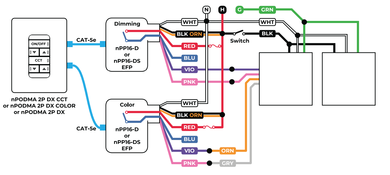
Alternatively, any two single-channel 0-10V wall dimmers installed in a 2-gang box will work.

Innerscene fixtures support sink and source current with auto-detect. Innerscene also supports log/linear options and digital trim controls using its built-in WiFi interface.

Acuity Brands' nLight™ wired system

Dual Channel Wiring

Two 0-10V dimmer switches (example: Lutron Diva™ or Nova T™)

Two 0-10V Wiring

Single channel 0-10/1-10V Controls

Innerscene fixtures support sink and source current with auto-detect. Innerscene also supports log/linear options and digital trim controls using its built-in WiFi interface.

Single channel 0-10V dimmer switch (example: Lutron DVSTV-WH, NTSTV-DV-WH, or Leviton IP710-DLZ)

Single Channel 0-10V Wiring

Diva and Nova T are trademarks of Lutron Electronics Company.

DMX Controls

Compatible DMX Controllers

Tested by Innerscene. Most DMX controllers are expected to work.

BrandModel
LevitonVarious
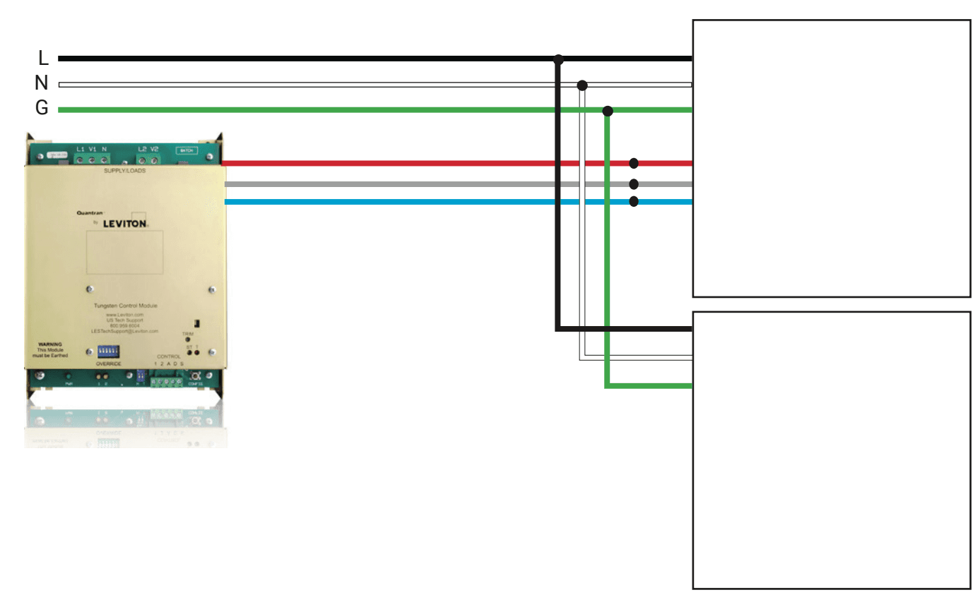
LutronHomeWorks™, Quantum™
PharosExpert Control™

™ trademarks are the property of their respective owners.

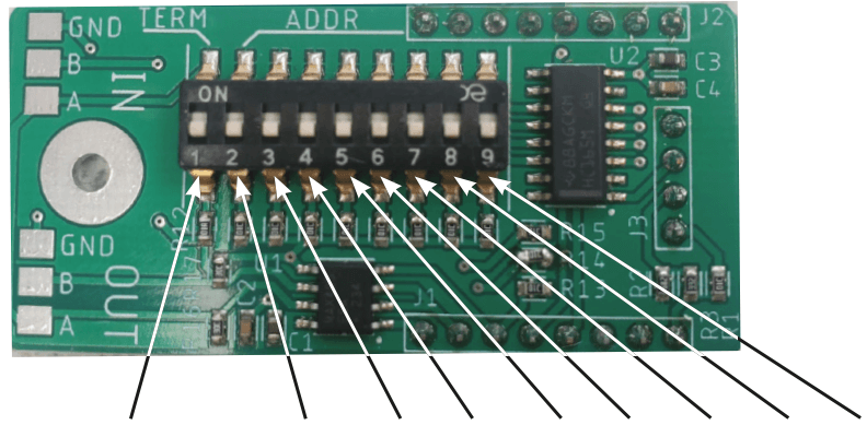
DMX Wiring and Setup

DMX Wiring

for Installers

  1. If the fixture is at the end of the signal run then fixture to Termination. DIP switch on Daugterboard postition 1 to ON/UP.
  2. Set the same starting channel on the fixture as the DMX controller/console using the DIP switch. The DIP switch use Binary encoding, for example, channel 17 is 0000010000.
  3. By default the switches at all set to OFF and will not respond to DMX signals.
  4. First channel is Intensity/Dimming. Second channel is Color/Tuning. For example, if starting channel is set to 17, channel 17 is Dimming control (Intensity), channel 18 is Color control (CT).

CIRCADIAN SKY DMX DAUGHERBOARD

DMX Daugherboard

DALI Controls

Compatible DALI-2 Controllers

Tested by Innerscene. Most DALI-2 DT8 Tc controllers are expected to work.

BrandModel
Helvar950 Router
LutronAthena™, HomeWorks™
OsramDALI MCU TW
PharosExpert Control™

™ trademarks are the property of their respective owners.

Caution: only DALI-2 DT8 Tc tunable white profile is supported. For dual address DALI-1 please contact Innerscene support line.

DALI-2 DT8 Tc System Wiring

DALI Wiring